Before a site drawing is fixed, one question decides the cabinet: how much shell goes to equipment, how much to batteries, and when does a single cabinet stop being enough? Two measured quantities answer it better than a product name — the rack units your 19-inch equipment occupies, and the battery volume your required back-up hours demand. Shell count, and whether the cabinet sits on a wall or a foundation, follows from that split.
Huijue's outdoor integrated cabinet range is built along that line. According to the equipment installed, a single cabin can be an equipment cabin, a battery cabin or a mixed cabin. A multi-cabin structure then combines those single cabins into an outdoor double cabin or triple cabin as the project needs (Outdoor Integrated Communication Cabinet). The outdoor integrated cabinet range adds two compartmented models on top of those classes: the dual-compartment OLT cabinet and the five-zone MINI cabinet. Working through them in that order shows where each type earns its place.
Three functional shells, combined into double or triple cabinets
The shell name describes what sits behind the door, not how many doors the cabinet has. An equipment cabin holds transmission hardware, a battery cabin holds the battery string and its rack, and a mixed cabin puts both in one enclosure. The series page describes the multi-cabin structure as a geometric combination of single cabins (series description). That is why "three-compartment cabinet" can mean several different physical products depending on the family.
| Shell arrangement | What the site gets | Sensible starting point |
|---|---|---|
| Single cabin, mixed | Equipment and batteries in one shell, separated internally | Small access nodes with short autonomy and few rack units |
| Single cabin, one function | Equipment or batteries, not both | Sites where the other functions are housed elsewhere |
| Double cabin | Two single cabins combined | Battery volume close to or larger than the equipment space |
| Triple cabin | The combination extended to three shells | Equipment growth planned, or power and batteries need separate treatment |
The OLT cabinet shows a two-part answer inside one body: a dual-compartment structure with an integrated compartment and an equipment compartment, and a front door with an optional rear door. The published page describes one 1500 W compressor air conditioner with an optional 300–3000 W unit; check that cooling figure against the current datasheet before it goes into a project specification. Counting this arrangement as one shell or two depends on whether you count bodies to transport and install or zones to maintain.
The MINI Cabinet: two equipment zones, power, battery and air conditioning
The MINI Cabinet's structure is finer than the series naming suggests. It is divided into two equipment compartments, a power supply area, a battery area and an air conditioning area, with front and rear door opening (MINI Cabinet). Five named zones sit inside three compartments: the compartments are the physical divisions, the areas are the functional blocks you design around. With a battery area to itself, the model belongs with the compartmented family rather than with the entry-level mixed cabin.
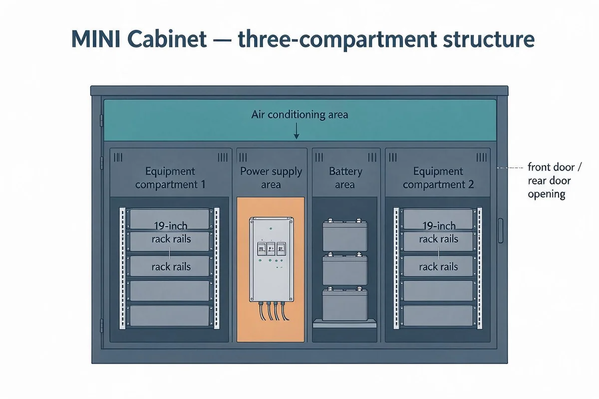
Inside, the cabinet arrives with columns, laminates, battery racks, air conditioning racks, door magnetic sensors and installation accessories (MINI Cabinet). That list tells you which hardware you are sizing around: a battery rack, an air conditioning rack and the equipment columns that form the 19-inch mounting plane. Cooling is one 2P wall-mounted air conditioner per cabinet on the same published page.
The arrangement also shows what a change in autonomy does. Back-up hours drive the battery area, not the whole footprint, so a longer autonomy first eats into the battery rack levels. When the required string no longer fits those levels, the design has left cabinet tuning and moved to shell count.
Selecting the shell type by the equipment-to-battery ratio
The comparison needs two currencies. Equipment is counted in rack units, with 1U equal to 44.45 mm of 19-inch mounting height. Batteries are counted first in ampere-hours at a stated discharge duration, then converted into the block count and the rack levels those blocks occupy. The balance between the two measures shows which way the shell should lean.
Step 1: add up rack units, not device count
List every 19-inch item the cabinet will hold: the OLT or switch, the media converter shelf, the ODF or distribution panel, the DC power and distribution unit, the monitoring unit, and any future slot already committed. Convert each to U, add the blanking and airflow space you will leave, then add roughly 15–20% as a working margin for cabling and later additions. That total is the equipment demand; the number of boxes is not.
Step 2: turn the back-up requirement into ampere-hours, then into rack levels
Divide the site's average DC load in kW by the DC bus voltage to get the discharge current. A 2.3 kW average load on a -48 V bus draws about 48 A. A 12 V 100 Ah block holds 4.8 kWh nominal, but its deliverable ampere-hours depend on the discharge duration it is rated for. Read the rating for the duration you plan to run — 8 hours in this example — and only then apply the usable depth you are prepared to design to, commonly 0.8 for a lead-acid string. On that basis, 48 A for 8 hours at 80% usable depth needs about 480 Ah of capacity rated at the 8-hour duration.
A -48 V bus is four 12 V blocks in series, giving 48 V at the block's own 100 Ah. To reach 480 Ah the string becomes five of those series runs in parallel: 20 blocks of 12 V 100 Ah, roughly 4.8 kWh per block and about 96 kWh nominal on the bus. Under the assumed 2U per block, 20 blocks take about 40U of rack height, which is five shelf levels at two blocks per level. That is already close to the full height of one 42U column before the equipment and power areas are counted.
These worked figures are illustrative assumptions: a constant 2.3 kW load, an 8-hour target, a battery rated at that same 8-hour duration, 80% usable depth, and 2U of rack height per 12 V 100 Ah block. Feed your own values into the same steps and the method still holds. Carrying the example to 20 blocks and 40U matters because it lands in the same currency as Step 1, so the two totals can be compared directly.
Step 3: read the ratio and choose the lean
The battery column in the table is a qualitative band read from block count and rack levels: a small set occupies one or two shelf levels, a moderate set three to five, and a large set five levels or more, where a dedicated battery shell usually beats sharing.
| Equipment U | Battery volume | Configuration to start the quote with |
|---|---|---|
| Roughly 10U or fewer, 2–4 h autonomy | Small: one or two shelf levels | Single mixed cabin |
| Around 15–25U | Moderate: three to five shelf levels | Mixed or dual-compartment cabinet, such as the OLT model |
| Around 15–25U | Large: five shelf levels or more | Double cabin: equipment shell plus battery shell |
| 30U or more, or planned growth | Moderate or more | Triple cabin: a third shell for equipment or power |
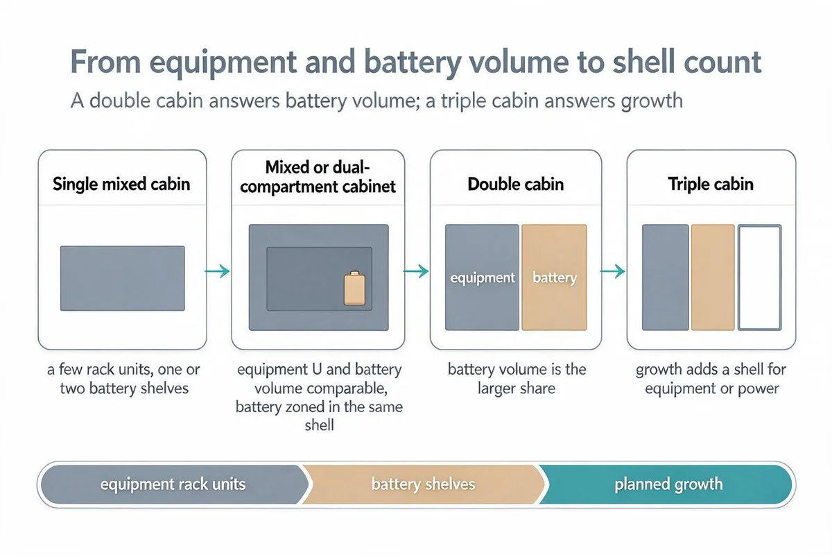
The table is a starting point rather than a rule. Watch the battery block count first, because battery racks are fixed-geometry hardware: once the string outgrows the shelf levels available, either the equipment side gives up space or the shell changes. Equipment growth leaves more room to manoeuvre, since a mixed cabin can absorb another rack unit or two until the battery area becomes the constraint.
Mounting options and bottom cable entry
Mounting follows the shell count and the site surface. The outdoor integrated cabinet can be wall-mounted or floor-mounted (Outdoor Integrated Cabinet), which covers the two situations most site plans present: a wall or structure that can take a bracket, or ground where a foundation can be built. The OLT cabinet is floor-mounted (OLT Equipment Cabinet).
Size the wall option from the installed weight rather than the empty shell. The inputs are the mass of the cabinet, its battery string and its equipment, plus the load the fixings must carry. A double or triple shell with a long battery string becomes a foundation decision in practice; the wall option suits smaller single-shell cabinets and sites where ground space is already taken.
These cabinets are built around bottom cable entry. The MINI Cabinet uses bottom entry with 8–16 incoming holes for power, fiber and cable (MINI Cabinet), a range set by configuration rather than a fixed count. Count routes before fixing the number: mains input, DC output to the equipment, fiber feeder, follow-on fiber, the earthing route, and any spare needed for a second operator each take a hole. Near the top of the range, the hole count becomes a non-standard configuration item for the drawing, not a field modification.
19-inch compatibility and the U limit
The MINI Cabinet supports 19-inch (IEC297) standard racks and equipment that meets the 19-inch installation space (MINI Cabinet), and the series standardizes on the same 19-inch method. In a compartmented cabinet the binding dimension is not the faceplate width but the column height left after the battery area and power area. A 42U figure describes a rack; the equipment compartments of a five-zone shell will not all offer 42U. The number to confirm from the drawing is the usable U per equipment zone, with the internal depth for 19-inch units and their cabling.
Reserve the top of each equipment zone for passive hardware and airflow. Check the depth of any rack-mounted unit, especially a deep DC power shelf, against the internal clear depth: standard 19-inch width fixes the rails and says nothing about whether a deep unit will close the front door of a short cabinet.
Front access, door opening, locks and alarms
Outdoor cabinet maintenance happens from the front, often at night and often with one person. The series provides full front-side operation with all cable entry and jumper connection carried out from the front (Outdoor Integrated Cabinet), so maintenance needs no rear working space. What the cabinet cannot supply is the space in front of it: leave enough width for a door that opens toward a wall or kerb, and enough clear zone for a sliding shelf.
The door package carries the field security. Doors use an embedded structure with tight gaps, an opening angle greater than 110° and a limiting structure that holds the door open. A three-point pull-rod and lock-plate lock takes an additional padlock on the series cabinet, and each door carries a door-open alarm sensor for environmental monitoring. The MINI page lists three-point fixed locks with screws set inside the cabinet, invisible from outside, and states the lockset's vandal resistance against the Class B requirement of GA/T 73-1994 (MINI Cabinet). Count alarm inputs by door, not by cabinet: a multi-door shell needs more than one sensor.
Strong and weak electricity separation
Power and signal share the cabinet without sharing the route. The series separates strong and weak electricity with dedicated wiring troughs and keeps all cable-entry and jumper work at the front (Outdoor Integrated Communication Cabinet). In the compartment split this becomes a drawing-stage constraint: the DC distribution output crosses from the power area into the equipment compartments, so the trough route should be settled before the cabinet is ordered rather than re-routed at commissioning.
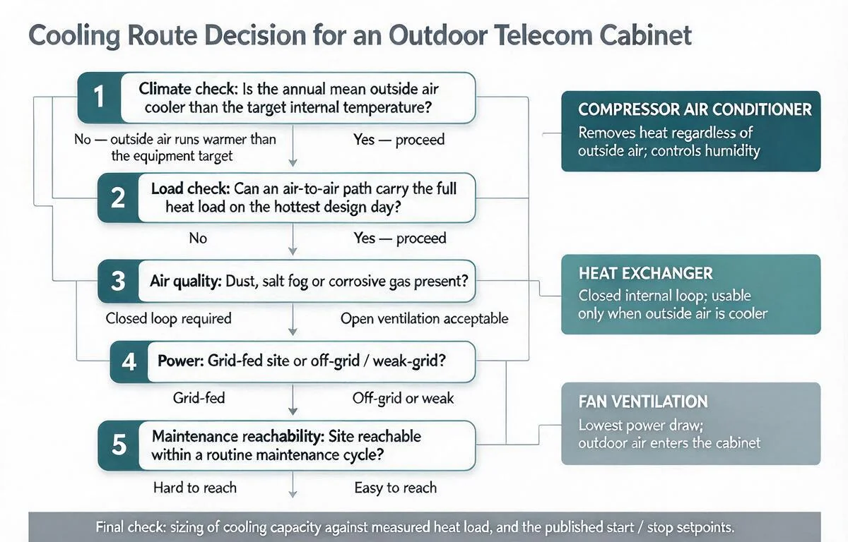
In hot or dusty climates the boundary between zones also does environmental work. The equipment compartment is separated from the battery compartment to insulate the equipment space thermally, while the battery side relies on its own thermal treatment. Block layout, insulation and shading are covered more fully in Huijue's articles on battery compartment thermal design and on choosing between a fan, heat exchanger and air conditioner. A mixed or two-compartment shell is a realistic option only when each zone's thermal design was decided alongside the ratio.
What to settle before ordering a non-standard cabinet
Non-standard cabinets can be customized, so the shell count, zone widths and hole count are all adjustable. The further the design moves from the standard model, the more of it has to arrive on the enquiry sheet. A complete request should carry:
- The equipment list in U, with depth for each 19-inch unit and the margin reserved.
- The required autonomy in hours, the average and peak DC load, and the DC bus voltage.
- The battery chemistry and block size if already decided; otherwise the autonomy and load are enough for a first sizing.
- The mounting surface and whether a foundation is available.
- The number and type of cable routes, with the bottom entry-hole count you need.
- The access side, the space you will leave, and the doors that need alarm sensors.
- The site condition that changes the design: coastal salt-laden air, sustained high temperature, dust exposure.
- The protection level you intend to verify at acceptance, and the test basis you will rely on.
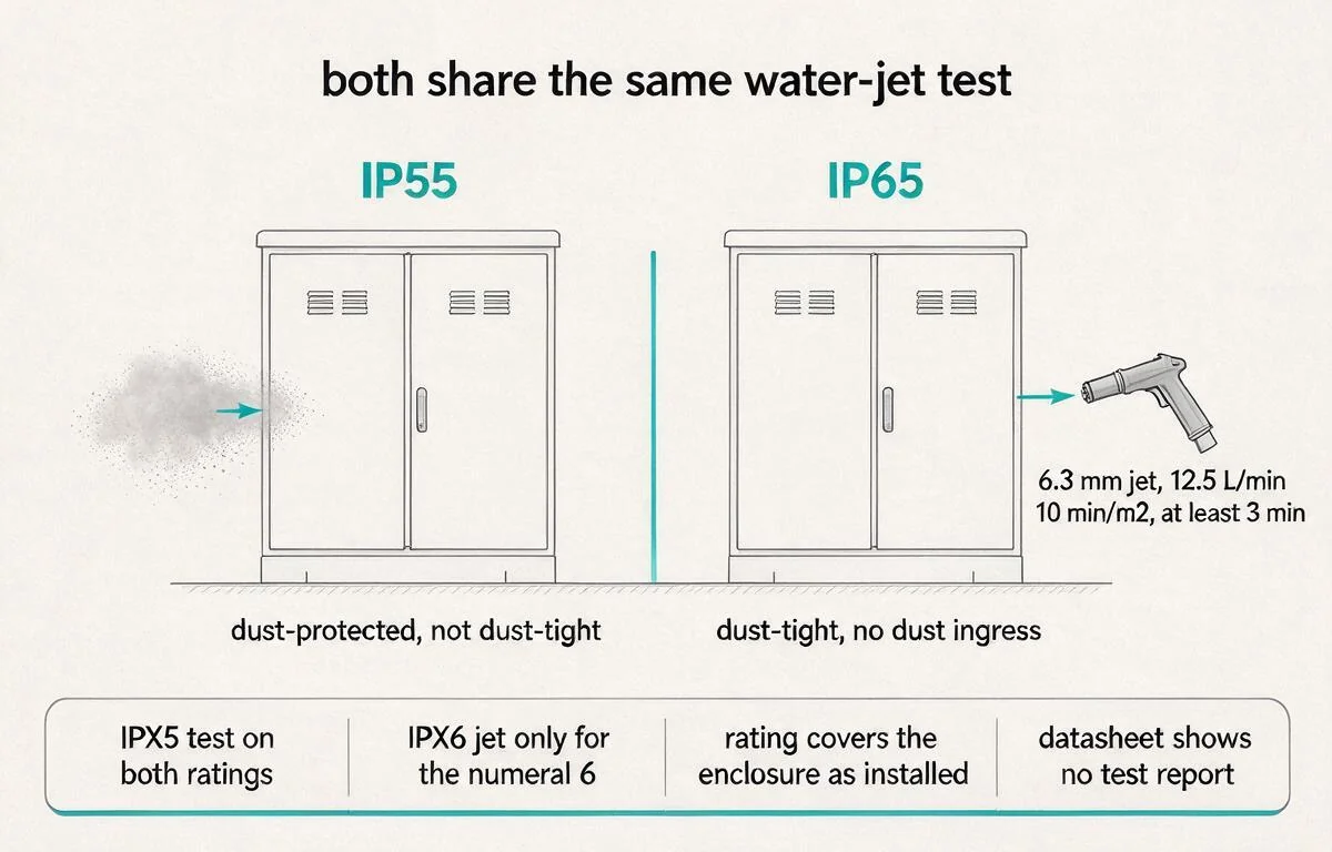
The published protection level for the MINI Cabinet is IP55 or higher, and the model page also states that it is rust-proof and corrosion-resistant, suitable for coastal areas (MINI Cabinet). Treat that as the enclosure's stated level and take the project acceptance value from the test record of the exact model and configuration. The two digits of the code do different jobs: the first rates protection against solid objects on a 0–6 scale, the second protection against liquids on a 0–9 scale; the IEC IP-ratings overview explains the scale, and the IEC 60529 standard holds the test conditions behind those numerals.
Three inputs get you to a usable configuration fastest: the equipment U total, the autonomy requirement with its load, and the mounting surface. With those, the ratio can be read and a single mixed, dual or triple configuration proposed, including the entry-hole count, the alarm inputs and any non-standard items the project needs. Send the site parameters and the sizing starts from a configuration rather than a catalogue page.
——END——